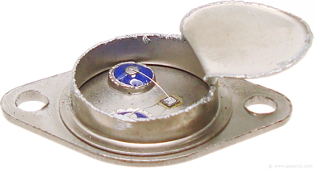


Manufacturers rarely specify the V CES voltage rating for the 2N3055. Sometimes the 100 V CBO breakdown voltage (the maximum voltage between collector and base, with the emitter open, an unrealistic arrangement in practical circuits) is given as the only voltage rating, which can cause confusion. The maximum collector-to-emitter voltage for the 2N3055, like other transistors, depends on the resistance path the external circuit provides between the base and emitter of the transistor with 100 ohms a 70 volt breakdown rating, V CER, and the Collector-Emitter Sustaining voltage, V CEO(sus), is given my ON Semiconductors. The frequency at which gain begins to drop off may be much lower, see below.ĢN3055 transistor internals. It often has a transition frequency of around 3.0 MHz and 6 MHz is typical for the 2N3055A at this frequency the calculated current gain (beta) drops to 1, indicating the transistor can no longer provide useful amplification in common emitter configuration. Packaged in a TO-3 case style, it is a 15 amp, 60 volt (or more, see below), 115 watt power transistor with a β (forward current gain) of 20 to 70 at a collector current of 4 A (this may be 100 to 200 when testing using a multimeter ).

The exact performance characteristics depend on the manufacturer and date before the move to the epitaxial base version in the mid-1970s the f T could be as low as 0.8 MHz, for example. A mica insulator electrically isolates the transistor case from the heatsink. 2N3055 transistor mounted on an aluminum heat sink.


 0 kommentar(er)
